ZEISS INSPECT Optical 3D
Free 3D Inspection Software - 3D Viewer with Mesh Processing Functionality
| FREE TRIAL |
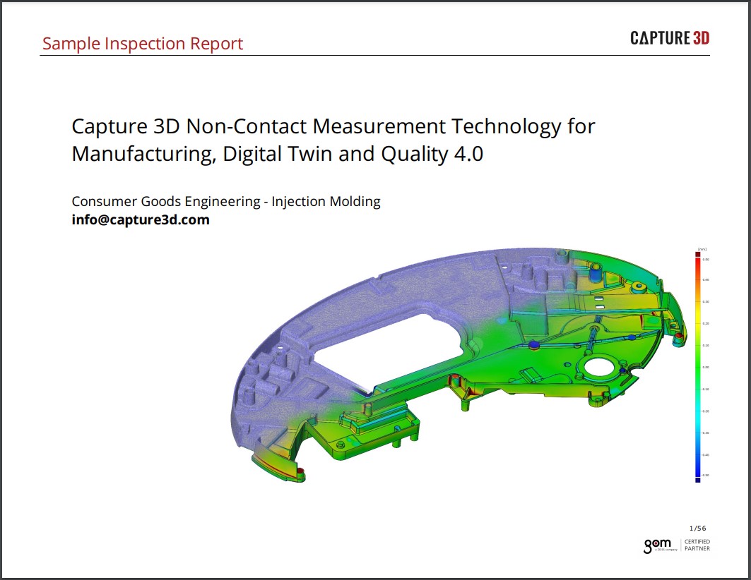
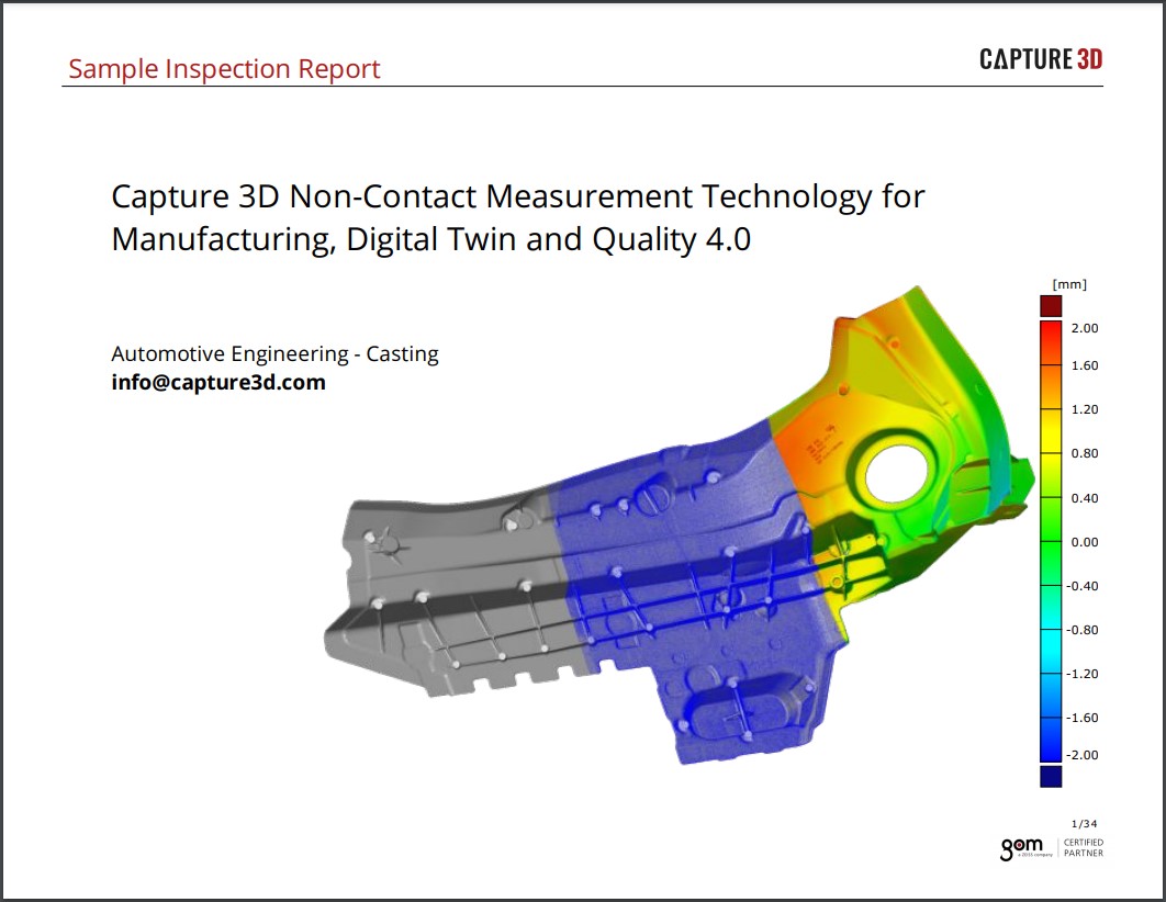
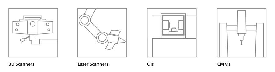
Free inspection software with over 158K downloads! ZEISS INSPECT Optical 3D is free mesh processing and inspection software for dimensional analysis of 3D point clouds from white light scanners, laser scanners, CTs and other sources. This software is entirely free to use, and results can be shared amongst departments, vendors, and/or customers for faster communication to help speed up the decision-making process.
ZEISS INSPECT Optical 3D contains all the evaluation tools necessary for an extensive analysis of parts and components. It is independently tested and certified by German and American national measurement laboratories (PTB, NIST). The accuracy of the evaluation software is verified by comparing the results obtained from the software with reference results. ZEISS INSPECT Optical 3D has been placed in class 1, the class of the smallest deviations.
 |
Comparison free ZEISS INSPECT Optical 3D and the full version of ZEISS INSPECT Optical 3D
ZEISS INSPECT Viewer |  ZEISS INSPECT Optical 3D ZEISS INSPECT Optical 3D |  ZEISS INSPECT Optical 3D ZEISS INSPECT Optical 3D Full Version | |
|---|---|---|---|
| View Projects |  |
|
|
| Edit Projects |  |
|
|
| CAD Import | |
|
|
| Mesh Editing | |
|
|
| Reporting | |
|
|
| 3D Inspection | |
|
|
| Native CAD Data | |
|
|
| Parametric Inspection | |
|
|
| Trend Analysis | |
|
|
| Scripting | |
|
|
| Digital Assembly | |
|
|
The free ZEISS INSPECT Optical 3D software is also a viewer for all measurement results that are created with ZEISS INSPECT Optical 3D.
System requirements |
|
| Minimum: Intel Core i3, 4 GB RAM, OpenGL-compatible graphics board (NVIDIA Quadro for optimized hardware rendering), |
|

ZEISS INSPECT is fully compatible with Windows 7® / Windows 8® / Windows 10® Operating System*.
Data Import |
|||
| CAD data | Measuring plans | Point clouds (3D scanner) | |
| • IGES | • ASCII | • G3D - ATOS | |
| • STEP 203/214 | • CSV | • STL | |
| • VDA | • ... | • ASCII | |
| • JT-Open | • POL | ||
| • STL | • PSL |
Highlighted Features |
|
Polygon Mesh3D meshes are calculated from 3D point clouds for visualization, simulation, reverse engineering, and CAD comparison. Meshes can be exported to a number of standard formats, such as STL, G3D, JT Open, ASCII, and PLY. Please note that in order to polygonize ATOS data, GOM Inspect Professional is required. |
 |
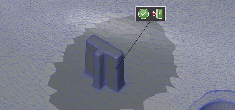
Mesh ProcessingPolygon meshes can be smoothed, thinned and refined. In addition, holes in the mesh can be filled and curvatures extracted. The mesh is processed using curvature-based algorithms and tolerances. The software provides the user with a live preview of each processing step before executing. |
 |
TraceabilityFrom element creation to final result, each step is comprehensively traced for process integrity. The exact creation parameters and measurement/point selection of any element are traced back to the origin. Parametric Inspection is a passive module in the free software package. All evaluation steps for an element can be traced but not adjusted or modified. For full Parametric Inspection, ZEISS INSPECT Optical 3D is required. |
|
CAD / Measurement Plan ImportOnly neutral CAD formats and measurement plans can be imported and read, such as IGES, STEP, and PLY. To import native formats like CATIA, NX, Solidworks and Pro/E, ZEISS INSPECT Optical 3D is required. The individual data formats are imported via drag & drop and are automatically identified and assigned by the software. |
 |
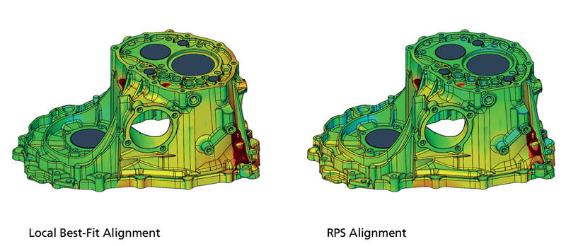
AlignmentContains all standard alignment functions. These include RPS alignment, hierarchical alignment based on geometry elements, reference points, and various best-fit procedures such as global best-fit and local best-fit. User-defined alignments can be displayed but not modified. For full access, ZEISS INSPECT Optical 3D is required so that customers can also use their own specific alignments, for example- turbine blades, balanced beams, or equalized nested alignments. |
 |
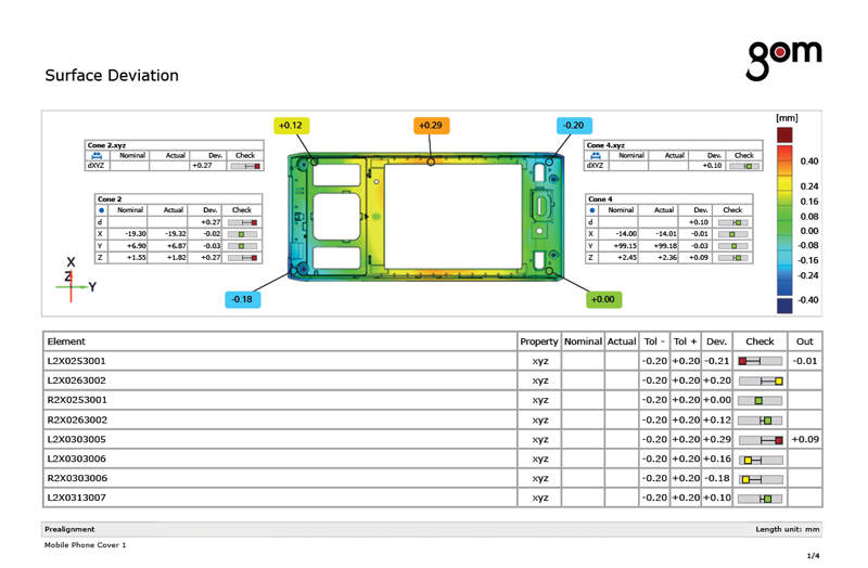
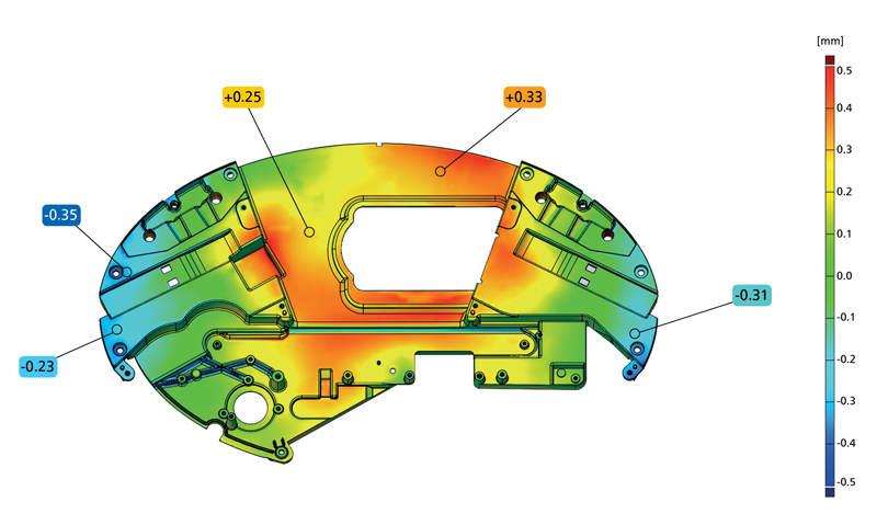
CAD ComparisonThe computed polygon meshes describe free-form surfaces and primitives. These can be verified by comparing surfaces with a technical drawing or directly to CAD. A 3D analysis of surfaces, as well as a 2D analysis of sections or points, can be implemented in the software. CAD-based generation of primitives such as lines, planes, circles, or cylinders is also possible. |
|
I-InspectThe I-Inspect button stands for "intelligent inspection" and guides operators through the inspection process. I-Inspect suggests suitable measurement principles and inspection criteria for the selected element. With I-Inspect, complex inspection tasks can be implemented quickly and easily. |
 |
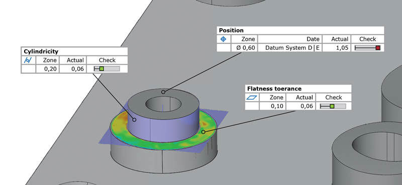
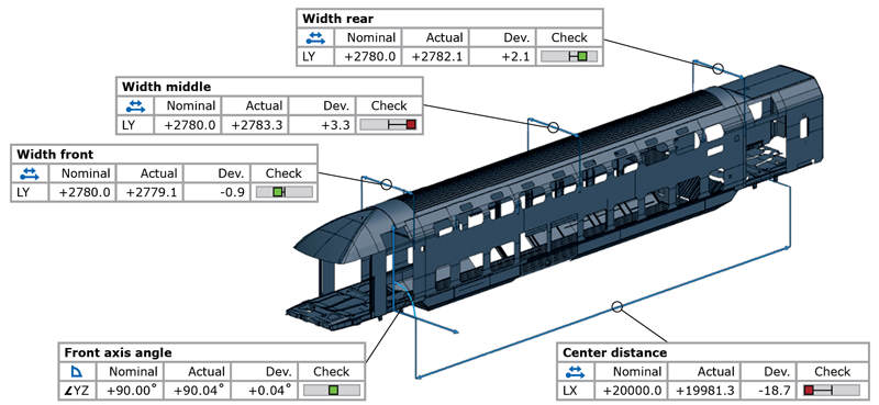
GD&T AnalysisIn contrast to basic measurement analysis, GD&T analysis focuses on the functional aspect of a part. The software conforms to ASME and ISO standards and allows extensive GD&T analysis, including planarity, parallelism and cylindricity, two-point distances, maximum material conditions, as well as position tolerance in local and global coordinate systems. |
 |
Trend, SPC and Deformation AnalysisTrend analysis helps monitor manufacturing and production trends to detect and prevent possible issues. This feature examines and reports the change in shape and morphing of geometry. These essential software tools are utilized to better understand manufacturing processes for a faster root cause analysis. Functions for trend analysis are fully integrated into the free software; however, to generate trend projects, the full version of ZEISS INSPECT Optical 3D is required. |
 |
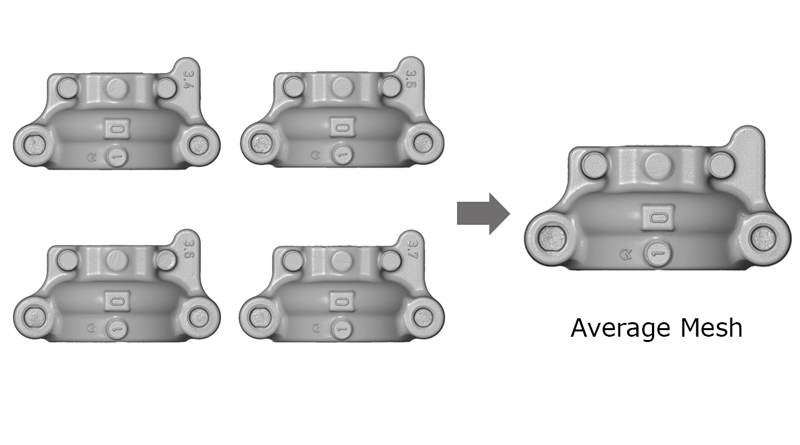
Golden MeshFor many applications, the Golden Mesh is required by either finding the best mesh or calculating an average mesh. The best mesh is an original mesh, which is determined to have the least deviation from an average data set. The average mesh is a new mesh, which is calculated based on a set of multiple meshes. When determined, the Golden Mesh can be exported as STL for reverse engineering to CAD or used as a reference for future part inspection. |
 |
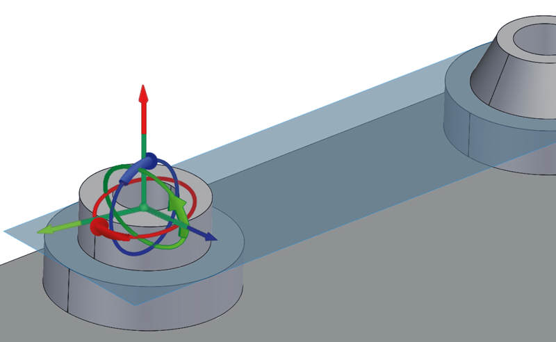
Local Coordinate SystemsThe local coordinate system in the software makes it possible to perform local or drawing-based evaluations. Hence, the dimensioning within a coordinate system is possible, standardized GD&T position analysis can be combined easily with local coordinate analysis in the same reference system and complex alignment strategies can be implemented. The local coordinate systems also form the basis for 6DoF analysis. |
 |
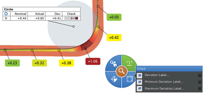
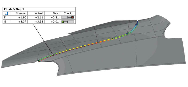
Curve-Based InspectionZEISS INSPECT Optical 3D closes the gap between point-based and surface-based inspection. Full-field digitized data is used to apply construction functions for curves and to visualize their individual properties. For example, Edge Curves can be captured, radii and character lines analyzed and spline curves created. Flush & Gap analysis is another element provided in curve-based inspection. |
 |
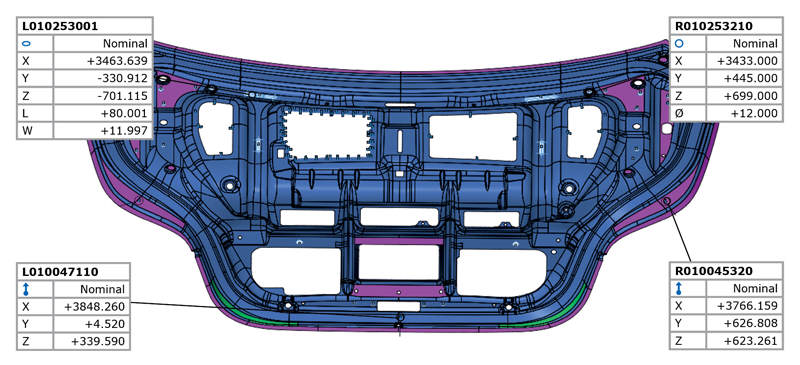
Point-Based InspectionAll evaluation functions can also be used on point clouds. For example, this includes measurement of distances between individual points and a comparison of points with the CAD model. Construction functions can then be applied to created geometry elements based on several points. This allows GD&T analysis of the generated elements, including flatness, cylindricity, or positional accuracy. |
 |
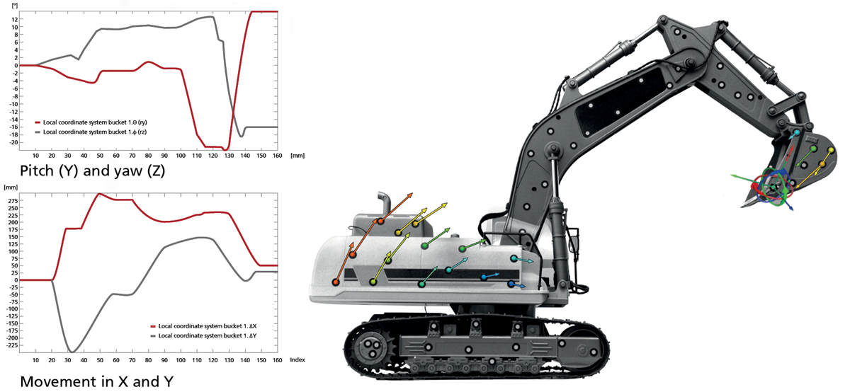
Point-Based Motion and Deformation AnalysisAnalysis of motion and deformation is carried out using a component concept. Points are divided into coherent groups and defined as components. Transformations or corrections to rigid body movements can then be calculated for these components. 6DoF (degrees of freedom) analysis can be applied to determine the translation and rotation movements in all directions. Vector fields then help visualize point movements and deformation over time.
|
 |
ReportingThe reporting module enables users to create reports containing snapshots, images, tables, diagrams, text and graphics. The results can be presented and edited in the user interface as well as exported to a PDF document. Custom templates are reusable, and each snapshot is stored in a report that can be restored in the 3D window. In order to personalize report pages, the full version of ZEISS INSPECT Optical 3D is required. |
 |

Languages |
|||||||
 |
 |
 |
 |
 |
 |
 |
 |
| English | Chinese | French | German | Italian | Japanese | Portuguese | Spanish |