
ATOS Professional Software
Intelligent and Comprehensive 3D Metrology Software for ATOS 3D Scanning Systems
Comprehensive software for ATOS 3D scanners. ATOS Professional includes all of the features of GOM Inspect Professional plus more. ATOS 3D scanning systems are engineered with advanced high-tech hardware coupled with intelligent software to offer a complete 3D metrology solution. ATOS Professional is created with intelligent software algorithms and in-depth analysis tools to produce high quality 3D data and precise dimensional measurements for engineering applications.
The smart user interface is knowledge base driven. It guides the operator through the entire scanning procedure and provides support for setting up new measuring tasks using the guided project creation feature.
-
- Application-related parameter settings and templates
- Optimizes start-up times for rapid measuring and evaluation
- Process integrity and traceability with automatic measurement checks and pre-defined templates
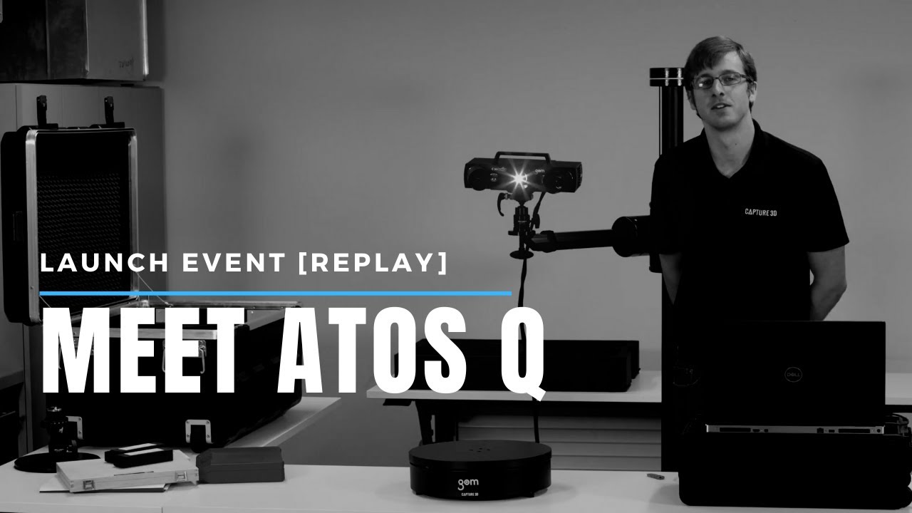
{youtube}EtMQA41Vlhs{/youtube}
Complete Workflow in 1 Software Platform
ATOS Professional software is used to operate the sensor head, process the 3D point cloud and to edit and post-process the data. The simple graphical user interface helps support today's demanding tasks in quality control, manufacturing processes and reverse engineering. ATOS Professional features include: Sensor control, polygon mesh generation and editing, sectioning, feature and character line detection and primitive generation. For quality control and result analysis, tools such as CAD data import, import of measuring plans, registration, full-field deviation plots, section-based analysis, deviation of individual points, calipers, angles and diameters and report creation are available.
Data Import |
|||
| CAD Data (standard) |
CAD data (native) | Measuring plans | Point clouds (3D scanner) |
| • IGES | • SolidWorks | • ASCII | • G3D - ATOS |
| • STEP 203/214 | • CATIA (v4, v5, v6) | • CSV | • STL |
| • VDA | • Siemens NX (Unigraphics) | • FTA | • ASCII |
| • JT-Open | • Pro/ENGINEER PRT | • ... | • POL |
| • STL | • Parasolid (.x_t* and .x_b*) | • PSL | |
| • SAT |
Highlighted Features |
|
|
High Quality 3D Mesh Data High quality 3D scan data minimizes time and costs associated with post-scanning processes- faster reverse engineering and faster inspections. ATOS Professional has unique algorithms that produce the highest 3D mesh data quality within the metrology industry combining small data size with accentuated fine details. |
 |
|
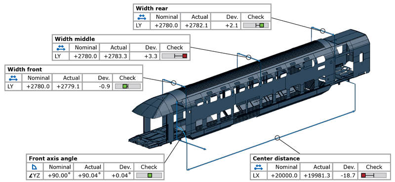
Self-Monitoring for Process Safety ATOS is a high-tech self-monitoring 3D scanning system that automatically verifies calibration status, transformation accuracy, environmental changes and part movement. This makes ATOS an ideal measuring solution in industrial production environments. |
 |
|
Dynamic Referencing Due to ATOS smart dynamic referencing, the object (part being measured) and the sensor can be freely moved or positioned during a scan project without the worries of sacrificing accuracy or data quality. The intelligent software automatically aligns each scan to create a 3D point cloud without leapfrogging. Additionally, the ATOS sensor and object do not need to be fixed in relation to each other. The intelligent software guides the user through the entire scanning process with instant 3D virtual visualizations on the monitor. |
 |
|
Motion Replay Movements from all axes of the motorization kit can be recorded without the need for programming. Thus, when users need to measure identical or similar parts, these measurement positions are simply played back. |
 |
| Parametric Inspection
Instead of using a macro engine, every single element knows its path of creation within the software structure. All processes and evaluation steps are completely traceable, mapped, interlinked, and can be easily modified or adjusted. A one-button feature updates all dependent elements automatically after changes. Free GOM Inspect: Parametric Inspection cannot be carried out in the free software. |
 |
|
Fast Real-Time Inspection with Simultaneous Evaluations ATOS Professional provides fast real-time inspection results after each scan. 3D surface deviation and inspection elements are instantly viewable within seconds. Inspection information is continuously derived and displayed from the complete pre-imported or manually created measuring plan and CAD during measurements. |
 |
| Traceability
From element creation to final result, each step is comprehensively traced for process integrity. The exact creation parameters and measurement/point selection of any element are traced back to the origin. Free GOM Inspect: Parametric Inspection is a passive module in the free software package. All evaluation steps for an element can be traced but not adjusted or modified.
|
|
| Teaching by Doing
Any completed evaluation can be easily applied to two or more parts to help save time and costs by reducing redundant tasks. Due to the parametric design, the software automatically stores each individual inspection step. All evaluation steps can be operated without scripting, previous planning or user intervention, so that no time is spent on programming. Free GOM Inspect: This is not available. |
 |
| CAD / Measurement Plan Import
Neutral CAD formats such as IGES, JT Open and STEP, as well as native formats like CATIA, NX, Solidworks and Pro/E, can be imported into GOM Inspect Professional at no extra cost. In addition, measurement plans in CSV, DMI, ASCII, IPP and FTA data formats can be imported as the basis for dimensioning and inspection. The individual data formats are imported via drag & drop and are automatically identified and assigned by the software. Free GOM Inspect: Only neutral CAD formats and measurement plans can be imported and read. |
 |
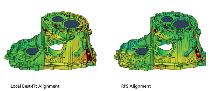
| Alignment
Contains all standard alignment functions. These include RPS alignment, hierarchical alignment based on geometry elements, reference points and various best-fit procedures such as global best-fit and local best fit. Customers can also use their own specific alignments, for example- turbine blades, balanced beam or equalized nested alignments. Free GOM Inspect: Comes with all standard alignment functions. User-defined alignments can be displayed, but not modified. |
 |
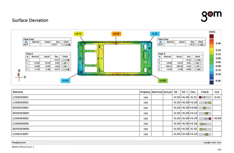
| CAD Comparison
The computed polygon meshes describe free-form surfaces and primitives. These can be verified by comparing surfaces with a technical drawing or directly to CAD. A 3D analysis of surfaces as well as a 2D analysis of sections or points can be implemented in the software. CAD based generation of primitives such as lines, planes, circles or cylinders is also possible. Free GOM Inspect: All inspection and CAD comparison tools are available. |
|
| I-Inspect
The I-Inspect button stands for "intelligent inspection" and guides operators through the inspection process. I-Inspect suggests suitable measurement principles and inspection criteria for the selected element. With I-Inspect, complex inspection tasks can be implemented quickily and easily. Free GOM Inspect: I-Inspect is available without any restrictions. |
 |
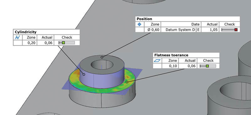
| GD&T Analysis
In contrast to basic measurement analysis, GD&T analysis focuses on the functional aspect of a part. The software conforms to ASME and ISO standards and allows extensive GD&T analysis, including planarity, parallelism and cylindricity, two-point distances, maximum material conditions as well as position tolerance in local and global coordinate systems. Free GOM Inspect: Full GD&T analysis functions are available. |
 |
| Trend, SPC and Deformation Analysis
Trend analysis helps monitor manufacturing and production trends to detect and prevent possible issues. This feature examines and reports the change in shape and morphing of geometry. These essential software tools are utilized to better understand manufacturing processes for a faster root cause analysis. With the software’s parametric inspection functionality these features can be applied to multiple data sets. This allows for full-field evaluation of several parts or stages within a single project and offers functionalities for determining statistical anaysis values such as Cp, Cpk, Pp, Ppk, Min, Max Avg and Sigma. Free GOM Inspect: Functions for trend analysis are fully intergrated in GOM Inspect; however, trend projects cannot be generated. |
 |
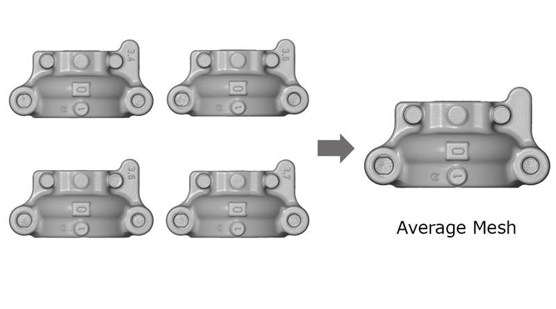
| Golden Mesh
For many applications, the Golden Mesh is required by either finding the best mesh or calculating an average mesh. The best mesh is an original mesh, which is determined to have the least deviation from an average data set. The average mesh is a new mesh, which is calculated based on a set of multiple meshes. When determined, the Golden Mesh can be exported as STL for reverse engineering to CAD or used as a reference for future part inspection. |
 |
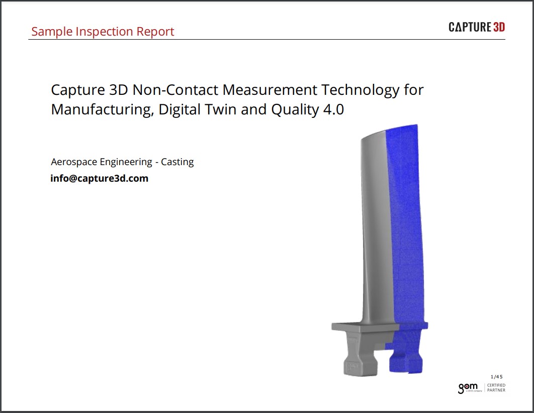
| Airfoil Inspection
ATOS Professional includes advanced industry-focused inspection evaluations. Native quality control functionality for the analysis of airfoils and turbine blades inclide: inspection of profile mean line, profile centroid and profile thickness of thurbine blades on the basis of 2D sections. The profile's center of gravity, radii and twist can also be calculated. Free GOM Inspect: Full airfoil inspection functionality is available. |
 |
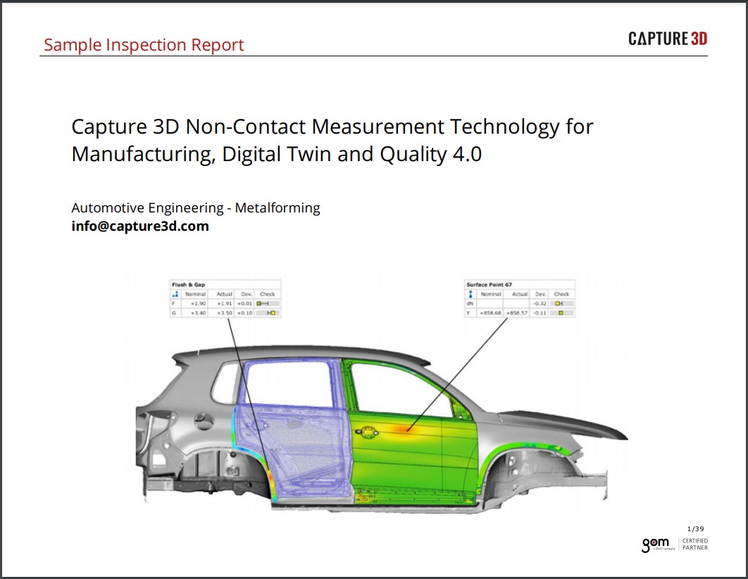
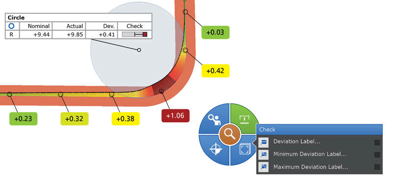
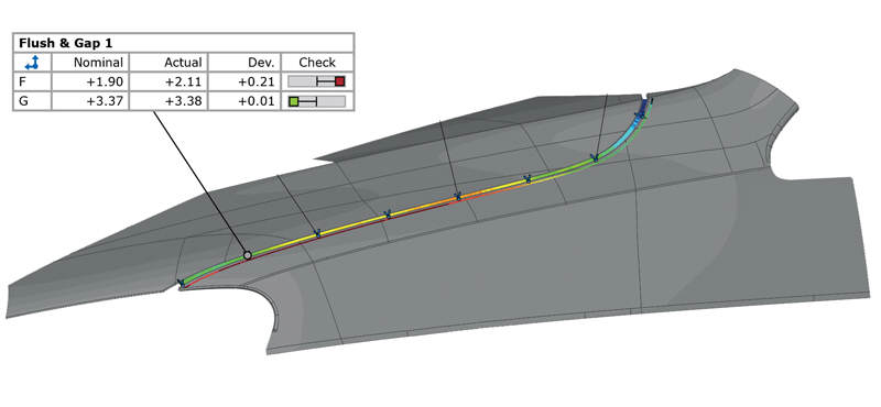
| Curve-Based Inspection
ATOS Professional closes the gap between point-based and surface-based inspection. Full-field digitized data is used to apply construction functions for curves and to visualize their individual properties. For example, Edge Curves can be captured, radii and character lines analyzed and spline curves created. Flush & Gap analysis is another element provided in curve-based inspection. Free GOM Inspect: All curve functions can be applied. |
 |
| Point-Based Inspection
All evaluation functions can also be used on point clouds. For example, this includes measurement of distances between individual points and a comparison of points with the CAD model. Construction functions can then be applied to created geometry elements based on several points. This allows GD&T analysis on the generated elements, including flatness, cylindricity or positional accuracy. Free GOM Inspect: All point based inspection functions can be applied. |
 |
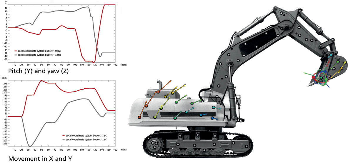
| Point-Based Motion and Deformation Analysis
Analysis of motion and deformation is carried out using a component concept. Points are divided into coherent groups and defined as components. Transformations or corrections to rigid body movements can then be calculated for these components. 6DoF (degrees of freedom) analysis can be applied to determine the translation and rotation movements in all directions. Vector fields then help visualize point movements and deformation over time. Free GOM Inspect: Existing data can be processed.
|
 |
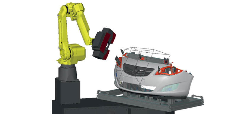
| Virtual Measuring Room (VMR) Add-On Module
VMR is a fully integrated solution to advance metrology automation. It enables the execution of automated measurements: import of measurement plans, offline and online programming, automatic sensor positioning, 3D measurement simulation, collision control, safety, data capturing, inspection and reporting. Free GOM Inspect: Can only be used as a viewer. |
 |
| Reporting
The reporting module enables users to create reports containing snapshots, images, tables, diagrams, text and graphics. The results can be presented and edited in the user interface as well as exported to a PDF document. Custom templates are reusable and each snapshot is stored in a report can be restored in the 3D window. Free GOM Inspect: Reporting functions are available; however, it is not possible to create personalized report pages. |
 |

Additional Modules |
|
| Live Module (Included with all ATOS Triple Scan systems and optional for other systems.)
In addition to high resolution and accurate 3D scanning and inspection, the Live workspace enables optical part tracking for position, back projection of features onto the part's surface for machining and welding, Touch Probe measurements, and deformation tracking analysis.
|
|
 |
|
| VMR - Virtual Measuring Room Module (Add-on)
The Virtual Measuring Room (VMR) has become an indispensable tool for automated non-contact 3D metrology. GOM offers an additional VMR software module within ATOS Professional software. With VMR, the user only has one single button necessary for complex measuring cell programming. This guarantees high functionality and reduced complexity. In addition, this enables increased workflow safety and considerable time saving. Build automated measurement environments virtually. Full simulation of measurement processes with both online and offline programming. Automated sensor positioning helps create scanning programs while the VMR takes care of collision detection and required inspection features. |
 |
| Kiosk Touchscreen Interface (VMR Add-on)
Kiosk is a Human Machine Interface (HMI) which provides graphics-based visualization for simplified interaction with Automated ATOS Inspection Systems. Kiosk automatically handles the complete measurement and inspection workflow providing easy-to-use shop floor operation eliminating the need for users to access Windows. Kiosk is easily job-task programmable for different departmental roles and can be configured for touch-screen operation. RFID and Bar Code readers can be integrated. |
 |