
ATOS 5 Airfoil
Blue Light 3D Scanner for Turbine Engine Components
Engineered for Aerospace and Ground Power Generation Industries Metrology
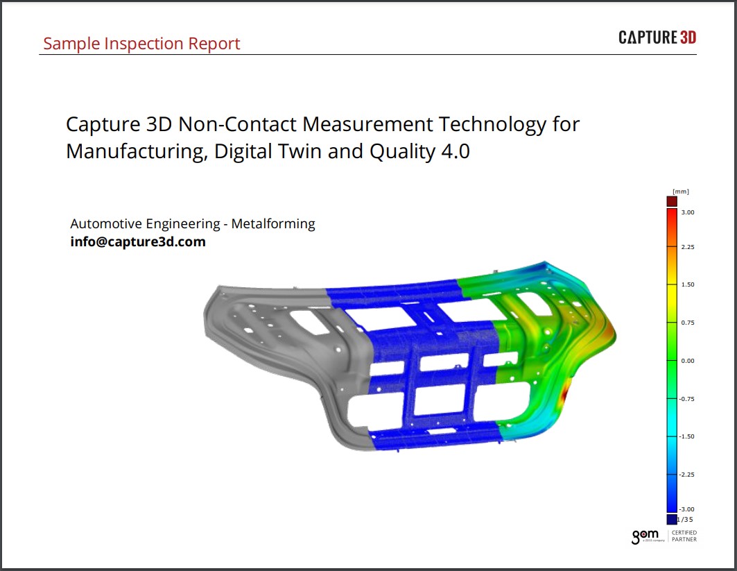
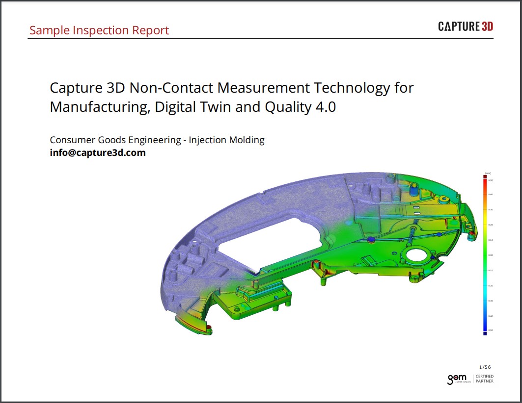
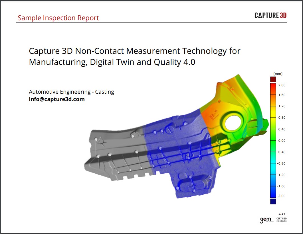
Engineered specifically for the Industrial Gas Turbine Industry, whether aerospace or ground powered applications, for providing accurate 3D measurements for airfoil inspection. The ATOS 5 Airfoil delivers high-precision data in a short measuring time even under harsh conditions. The full-field 3D measuring data allows comprehensive process and quality control, visualizing hidden errors and thus speeding up production processes.


|
Blue Light Equalizer Uniform, non-coherent, speckle-free light |
High-speed 3D scanning Measurements as fast as 0.2 seconds |
|
Optimized working distance Highest data quality down to the smallest detail |
Airfoil inspection software Functionalities engineered for inspecting airfoil sections |
|
High detail resolution Projection of very small fringes per unit area |
Bright LED light source 1.5 times brighter |
|
Low noise level Precise coverage of complex geometries |
Fast data processing Fiber optic cables and robust connectors |
 |
 |
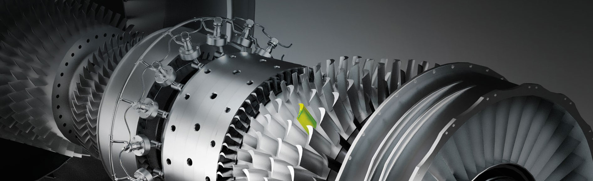
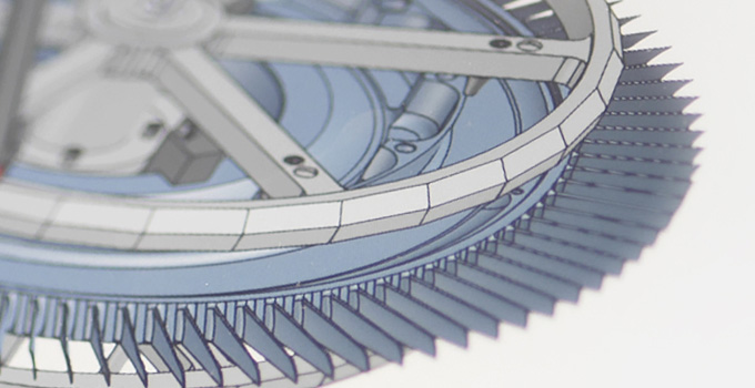
High-speed technologyWith its optimized working distance for small measuring areas and its extremely high stability, ATOS 5 for Airfoil delivers high-precision data for manual and automated applications. From fan blades to turbine blades or blisks and drums to vanes (NGVs, OGVs, IGVs) and power trains, the full-field 3D measuring data allows reliable quality control, visualizing hidden errors and thus accelerating production, maintenance, and repair processes. |
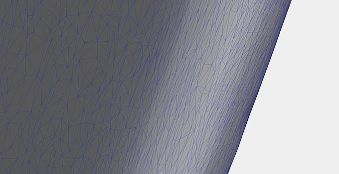
Highest data qualityWith its powerful light source, ATOS 5 delivers high-precision data for a diverse range of manual and automated applications, from tools and molds to plastic and metal parts. The ZEISS data quality is particularly evident in the detail sharpness of the 3D models, for example, in the precise display of the smallest details, rib structures, narrow radii, or hemmed edges. |
Speed up your process3D scanning times of about one hour for blisks and less than 20 minutes for fan blades result from data acquisition in less than a fifth of a second. |
Achieve the highest data qualityATOS 5 for Airfoil delivers high-precision full-field data for comprehensive process and quality control of fan blades, turbine blades, blisks and different vanes (NGVs, OGVs, IGVs). The data quality provided by the sensor meets the high requirements of the industry. |
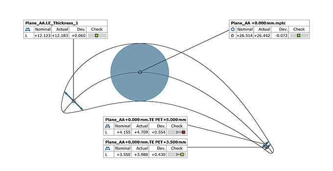
Airfoil Inspection Features
ZEISS INSPECT Airfoil has a complete set of airfoil inspection functionalities. The inspection principles include standard and customizable options to meet different engineering standards and types of airfoil drawings. The user-defined inspection principle (UDIP) enables fast, standardized and efficient inspections of airfoil sections.
 |
 |
|
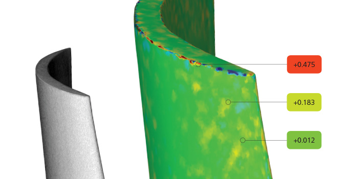
Surface Comparison A 3D representation of surface deviations to the CAD or master mesh is standard in ZEISS technology. Surface comparisons are typically used when developing new products to search for issues in the manufacturing process. Comparisons can be made in multiple alignments including best-fit to CAD or RPS. This powerful tool reveals product details that traditional tools cannot provide. |
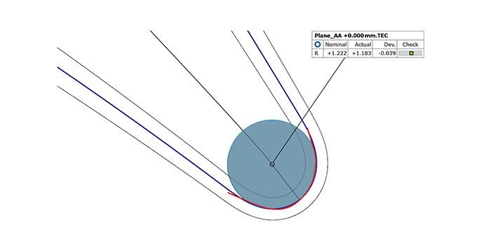
Edge Points and Edge Circles Edge point creation is a standard functionality and is determined by the pierce point of the camber line at the leading or trailing edge with the suction and pressure side of the airfoil. Expert parameters allow moving points along the camber line. Edge circles are also automatic and generate elements at the leading or trailing edge of the airfoil. |
|
|
 |
|
Thicknesses Standard functionality that creates thicknesses at the leading or trailing edge of the airfoil. The simple dialog prompts a distance value at which the thickness is to be taken from the edge point. Different options allow the measurement to be traced along the camber line. Traditional thicknesses at predefined drawing angles can also be created. A maximum airfoil thickness check is also available using the distance or maximum inscribed circle method |
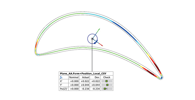
Form and Position Checks The software enables a flexible way to evaluate form and position of airfoil sections to meet end-user needs. Evaluation techniques of the actual section data can be compared using Chebyshev, Gaussian or best-fit by tolerance methods. The software can also compare the results with changing tolerance regions where tolerances are different across areas of the airfoil sections. |